Hi Alan,
Often its the way that simply cleaning up the connections fixes things.
So this evening I popped the tank off and replaced the HT leads. Whilst doing so I measured the resistance on the green wire...183 ohms so it's a bit on the low side.
183 ohms is low, whilst the bike starts OK i guess you can just keep an eye on it and plan to rewind over the winter perhaps.
Was the scope trace with the green wire disconnected? you say when kicking over?
///////////////////////////////////////////////////////
For the benefit of future readers of the post.
Its instructive to measure the generator with the engine running at constant rpm with everything connected.
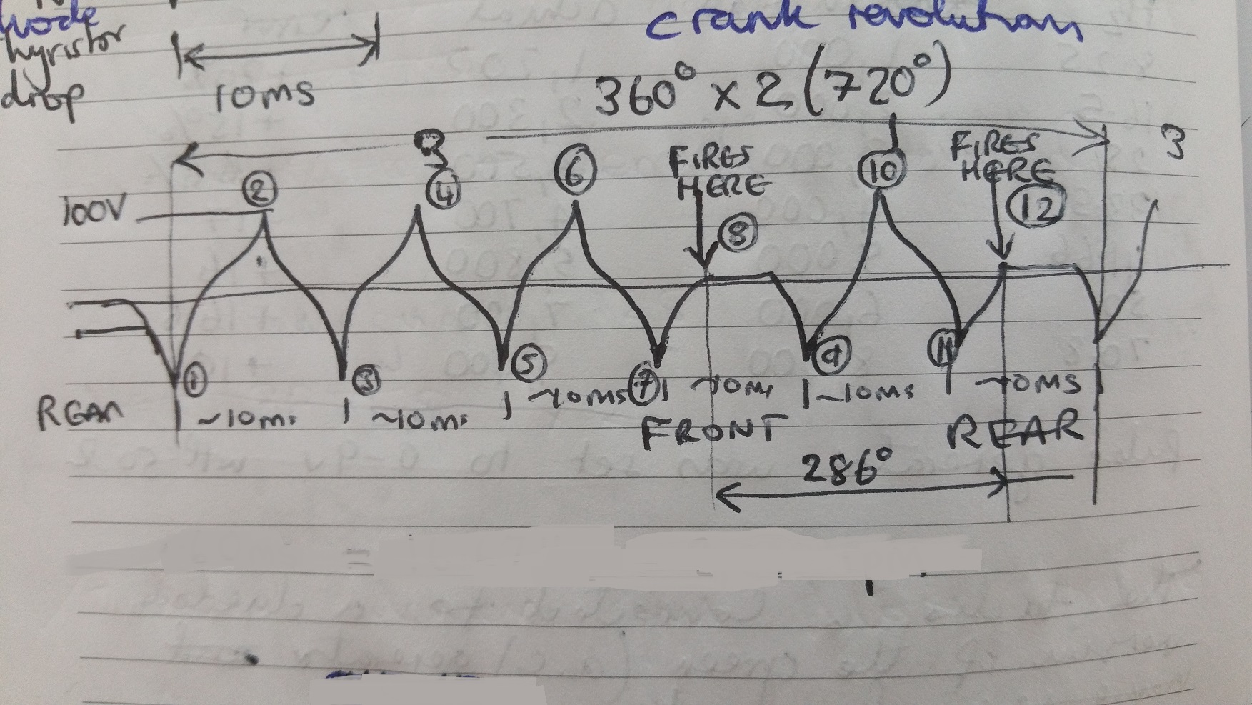
Please see my really scrappy drawing, this has annotations which are useful.
- Generator.jpg (504.52 KiB) Viewed 6012 times
If you measure the waveform with the engine running you will see that it has 12 distinct phases in 720 degrees of crank revolution this is obvious because the generator rotor has 6 magnets If we take as our reference the passing of the magnet just after the rear cylinder has fired, we see an alternating waveform with positive peaks of around 100V at idle. This is not a conventional generator sinusoidal waveform because the circuit is driving a capacitive load. At cycle 8 we notice that the waveform is clamped to 1V, this is the front cylinder firing, the thyristor in the transducer triggers and shorts the green wire, thus discharging the capacitor of the front transducer and creating the spark through the CDI coil. The thyristor continues to clamp the generator until the generator voltage goes negative at phase 9. The rear cylinder fires at phase 12.
All the peaks should be the same, of particular interest is the peak just before cylinder 2 fires. A possible critisicm of the design is that the energy available to cylinder 2 is compromised and really a twin should have an CDI generator winding for each cylinder.
It is important that clamping only occurs in the phases shown, there is no wasted spark, that the clamp forward voltage is not more than about 1V. The negative peaks play no part in the ignition save to allow the thyristor to switch off. The transducers must never be operated from a d.c 12V source. Missing trigger will be evident. However the thyristor may trigger and discharge the capacitor but still there might be no spark. To see the spark needs the inductive pickup of the strobe gun (if you have it) exposed to the oscilloscope or some other inductive pickup. Now to increase the rpm and confirm that the waveform doesn't change in its form, the peaks should not collapse.
I can measure with some accuracy that the firing angle between cylinder 1 and 2 does not deviate from its ideal 286.7 degrees more than a few degrees.
Mark


