regulator wiring
-
mad muller
- Posts: 206
- Joined: 19 Aug 2011 11:29
- Location: liverpool, england
regulator wiring
having some issues with the charging system , tried another battery but same prob , even after a long run battery seems to drain not charge, the wires to the regulator are two yellow one red one brown, looking at the wiring diagram this does not check out , its original regulator with a red plastic top were the spade connectors go in , its a starting motor late type sport , if anyone has same and have a look much appreciated, not sure if previouse owner has wired it right it all works lights etc , just not charging , have put the meter across the batt with engine running and volts read 13.5 but still not sure with the regulator wiring any help appreciated. muller.
Re: regulator wiring
There are two types of regulator/rectifier. The earlier type is a half wave split or centre tapped single phase and the later is a full wave single phase.
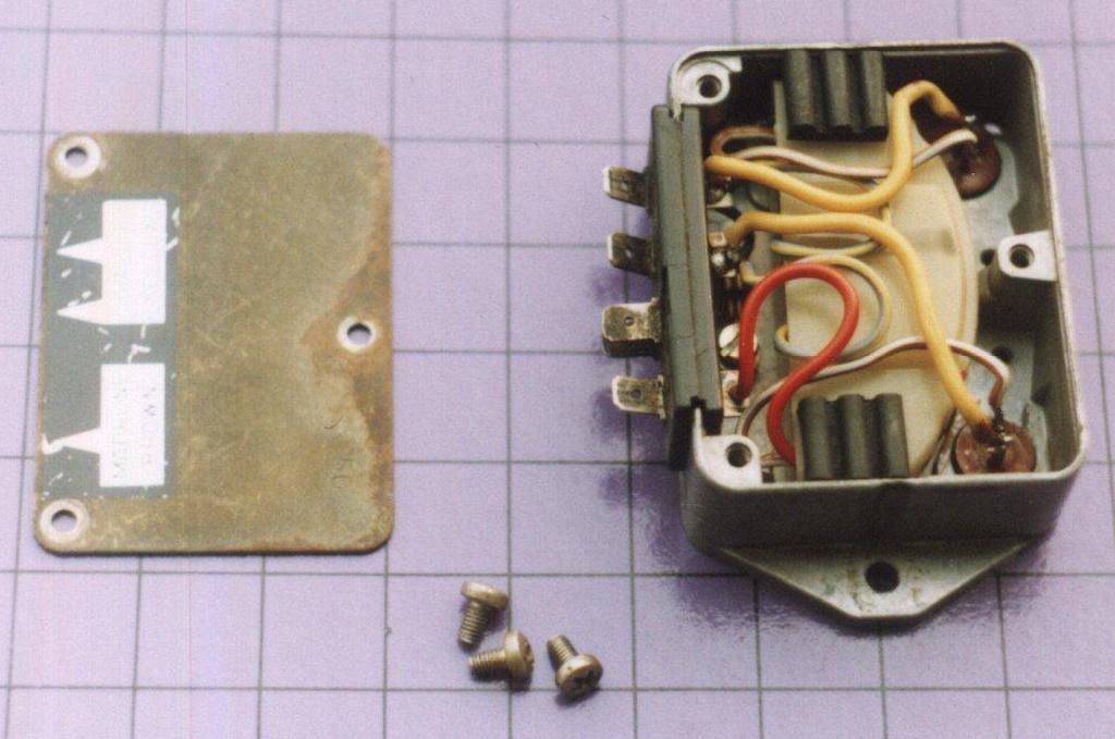
On the early type, only three terminals on the regulator are wired internally. The body of the regulator is ground, the Yellow terminals are the two phase inputs from the alternator and the Brown is battery voltage switched via the ignition. With the ignition on you should read full battery voltage between this terminal and the body of the regulator/rectifier. The dual terminals marked 'Rosso' are unconnected internally. The Red lead from the alternator may connect to here and then on to the fuse panel or connect direct to the fuse panel depending on model. Regulation/rectification is done on the negative side of the battery.

The later type of regulator/rectifier works differently. There is no Red wire from the alternator, just two Yellows and the Red wire is the positive output to the battery (via the fuse panel). The Brown is still fed via the ignition.
In both cases the voltage on the Brown wire should measure as battery voltage in order to charge. A poor connection here, or a faulty ignition switch can give no a or poor charging.
It's possible for a bike to start easily, but not charge correctly due to SOME magnets in the rotor being weak.
On the early type, only three terminals on the regulator are wired internally. The body of the regulator is ground, the Yellow terminals are the two phase inputs from the alternator and the Brown is battery voltage switched via the ignition. With the ignition on you should read full battery voltage between this terminal and the body of the regulator/rectifier. The dual terminals marked 'Rosso' are unconnected internally. The Red lead from the alternator may connect to here and then on to the fuse panel or connect direct to the fuse panel depending on model. Regulation/rectification is done on the negative side of the battery.
The later type of regulator/rectifier works differently. There is no Red wire from the alternator, just two Yellows and the Red wire is the positive output to the battery (via the fuse panel). The Brown is still fed via the ignition.
In both cases the voltage on the Brown wire should measure as battery voltage in order to charge. A poor connection here, or a faulty ignition switch can give no a or poor charging.
It's possible for a bike to start easily, but not charge correctly due to SOME magnets in the rotor being weak.
Paul Compton
http://www.morini-mania.co.uk
http://www.youtube.com/user/EVguru
http://www.morini-mania.co.uk
http://www.youtube.com/user/EVguru
-
mad muller
- Posts: 206
- Joined: 19 Aug 2011 11:29
- Location: liverpool, england
Re: regulator wiring
thanks for a very informative response EV, images are a real help , will check out connections and put a meter on it, also have a look at ignition switch, iam probably looking at the early wiring diagram that's whats thrown me a bit , thanks again a great help. muller.
-
sheddweller
- Posts: 48
- Joined: 01 Aug 2010 16:28
- Location: Sunshine Coast, Queensland, Australia.
Re: regulator wiring
Paul,
I couldn't read the markings on the red plastic above the spades in the photo you posted but you mention 2 spades marked 'Rosso'. The reg/rec that came spare with my bike looks to be the same as the one you photographed, but mine are marked G G R +B L C. Would you mind listing the connections to each. If my Reg/Rec is a differnt model, do those spade titles mean it is not compatible with a 350 Elec start with Yellow yellow, Red, Green and white wires from the Alternator?
Thanks
Garry Roberts