appreciate the trouble you've went to but i still need an actual phot0 of the regulator as fitted on the bike to see how the 3 yellow wires connect onto the connector.
i'm not sure if mine is wired up correctly and i don't want to burn the harness through overheating of the loom.
like everything else , a diagram was made before the "normal" domestic type terminal block was removed. Then in the middle of putting on a temporary set of connectors so that i could swap rectifiers at will to see what one was defective , my pal pulled the wiring too hard and out popped the wires from the new connectors. Because they are all the same colour i'm not sure if he has them in the right place, thats why i need a photo.
so really i'm looking for someone who has the black or white "t" type connector on the 3 yellow wires.fAILING THAT I'D NEED SOME ONE TO TELL ME HOW THESE WIRES RELATE TO THE 3 PIN PLUG HALFWAY DOWN THE FRAME(from alternator)
in the meantime i'll study the wiring diagram if i can find it
nearest pic i can get is from the manual on page 238 but not enough detail
just realised that what you call a choc block i call something else.
WHAT A PILE OF DIY crap

to put on a bike as an upgrade. I thought it had been done as a
diy job. Now i know that it was done on purpose i'll think about checking that plug halfway down the frame i was referring to.
this was the type fitted to the end of the 3 yellow wires on my bike
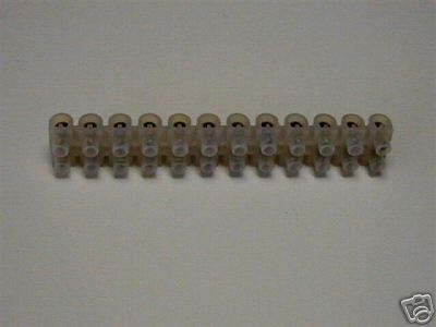
- connector-block-12-section-30-amp-922-p.jpg (11.41 KiB) Viewed 5757 times
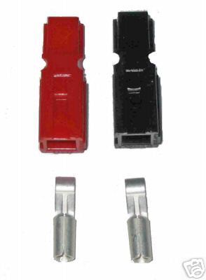
but i think i'll replace the diy warranty one with these
GENUINE ANDERSON 30 amp POWERPOLE CONNECTORS
- GENUINE ANDERSON 30 amp POWERPOLE CONNECTORS
GENUINE ANDERSON 30 amp POWERPOLE CONNECTORS - 068d_1.jpg (10.26 KiB) Viewed 5739 times
ebay about £6 for a set of five male and female with connectors
if the domesic type block was fitted as a warranty upgrade (30 amp block connector) chances are the connector i was talking about , that is, just at the removable frame cover half way down the left hand side is probably not up to handling the load either.
As i said earlier , on the other loom i looked at this was showing signs of overheating.
i've trawled the manual , i must be blind,or senile , where's the wiring diagram schematic

so any photos of the rectifier and yellow wires connecting ?, please
