Installing Elekronik Sasche MHP Digital Ignition in 500W
Posted: 25 Jul 2020 01:44
I have thrown in the towel trying to get the stock Ducati Electronica ignition to function reliably on my 1979 Moto Morini 500W.
The kit arrived yesterday via DHL including a pair of Dyna mini coils.
https://www.elektronik-sachse.de/shopsy ... i-500.html
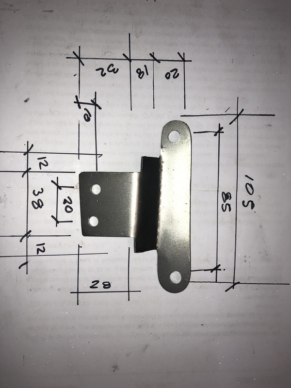
Installation is straightforward with the only challenge mounting the Dyna coils. I made up some brackets out of 18 gauge stainless steel sheet to tuck the coils into the positions previously occupied by the stock transducers.
To install the system simply disconnect the wires supplying the transducers;

green wire from fuse box to transducer with a jumper green to second transducer is disconnected, I just pulled the green wire out of the fuse box and folded it over a harness sheathing and zip tied it, same at the headstock area, folded green wires back against a harness and zip tied wire. My bike has the white ground wire connecting the two transducers and the continues to the fuse box, again remove white wire from fuse box, fold over and zip tie, ditto at the heads stock area.
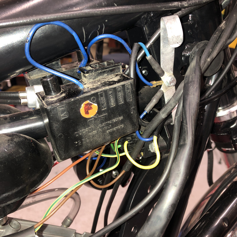
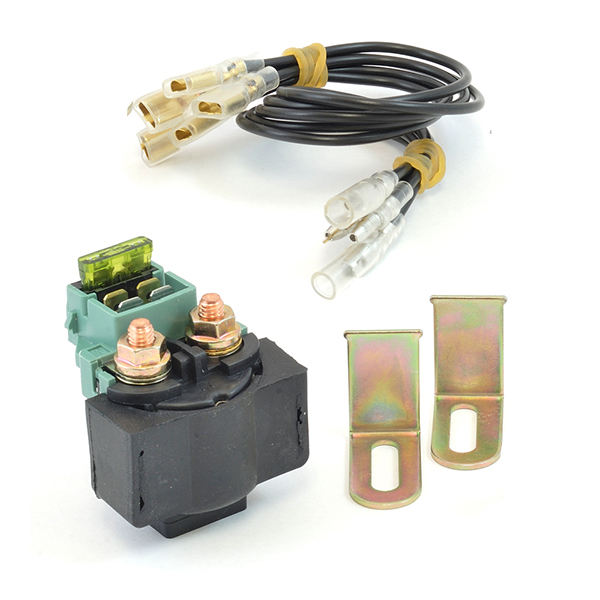
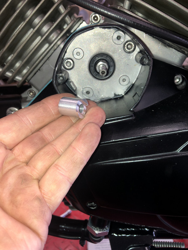
Remove the pick up inspection plate, remove the 8mm nut (11mm socket head) securing the pick up rotating magnet, remove nut, special spacer washer and magnet, remove the two alan head fasteners retaining the pick-up assembly and remove the pick up assembly, disconnect the two red wires up to the transducers and then unplug the grey wire on the left hand transducer that supplies the tachometer. The special washer will not be used with the new system, only the nut.
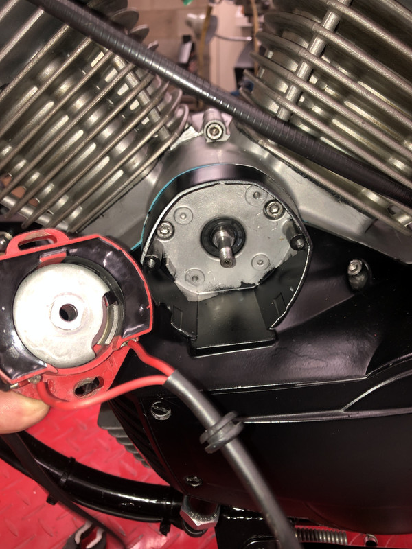
Remove the two transducers, Remove the high tension leads from the transducers to reuse onto the new Dyna coils.
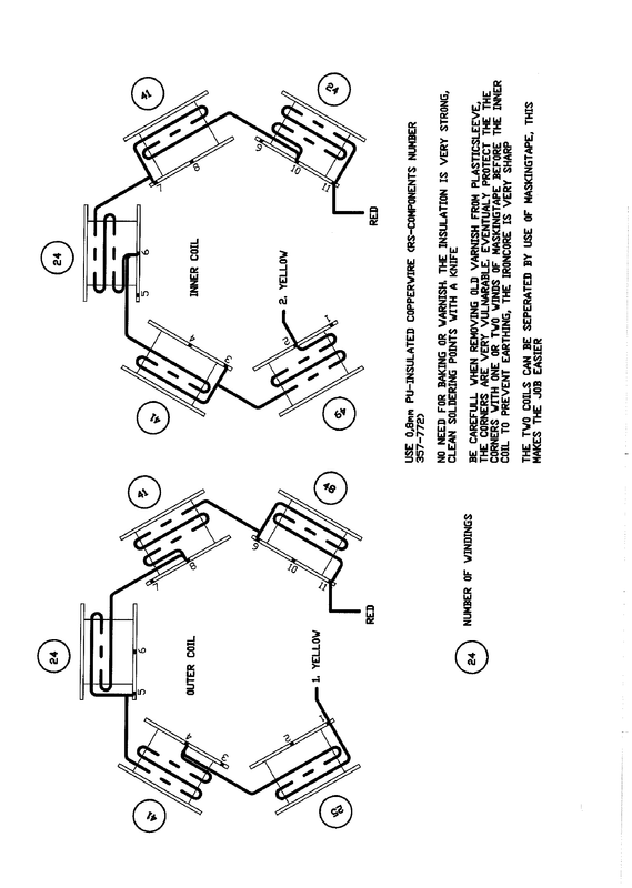
The two yellow wires from the original stator remain installed to the regulator / rectifier to continue to charge the battery.
The brackets for the Dyna coils were cut out of flat stainless sheet with a cut off wheel in a 4" grinder and finished with a flat file. Two 6mm holes for the coils and two 6mm holes to match the original transducer frame mounts.
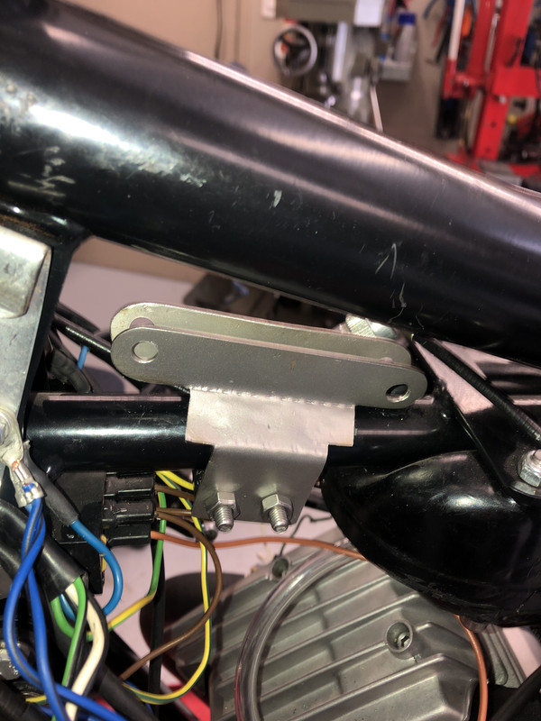


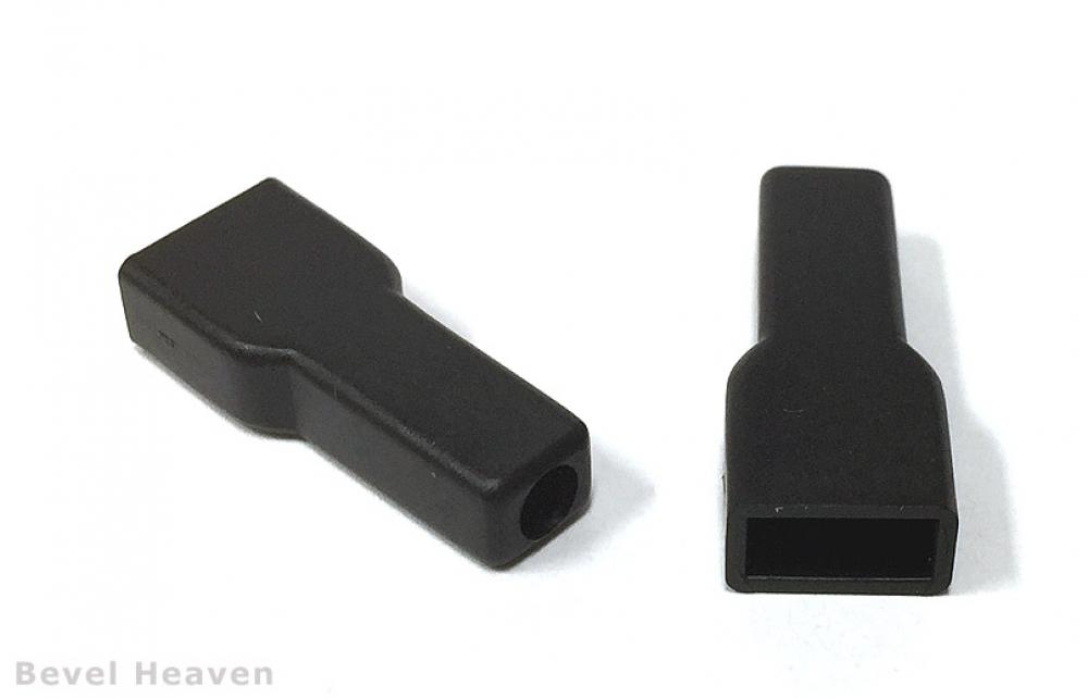
The Dyna coils are dampened with rubber bungs I had from other projects. There is also a thick rubber washer between the two brackets at each hole through which the coils are secured. I used 6mm threaded rod with a nylock nut on each end to through bolt the two coils through the brackets. before bolting the coils together I installed the high tensions leads with the new rubber boots and plug clips crimped onto the ends of the high tension wires.
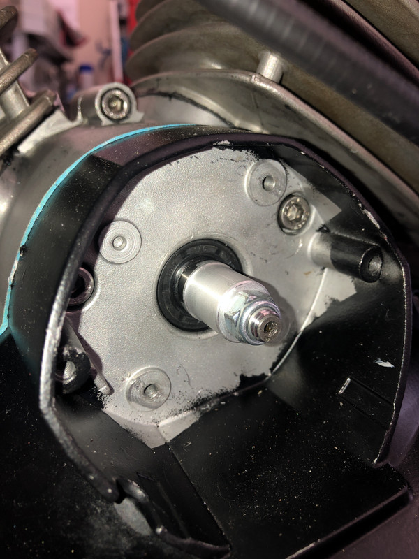
I then moved on to the pick up plate installation, install the new supplied steel spacer over the end of the cam shaft
and reinstall the nut over the protruding end of the cam shaft (no special washer used here)
The new supplied pick up plate with the LED sensors was installed using the two new alan head fasteners and washers. Attached to the new pick up plate is a four wire harness with a new rubber grommet, run the new harness up the front frame rail. I then ran the remainder of the harness to the space between the rear fender and battery.
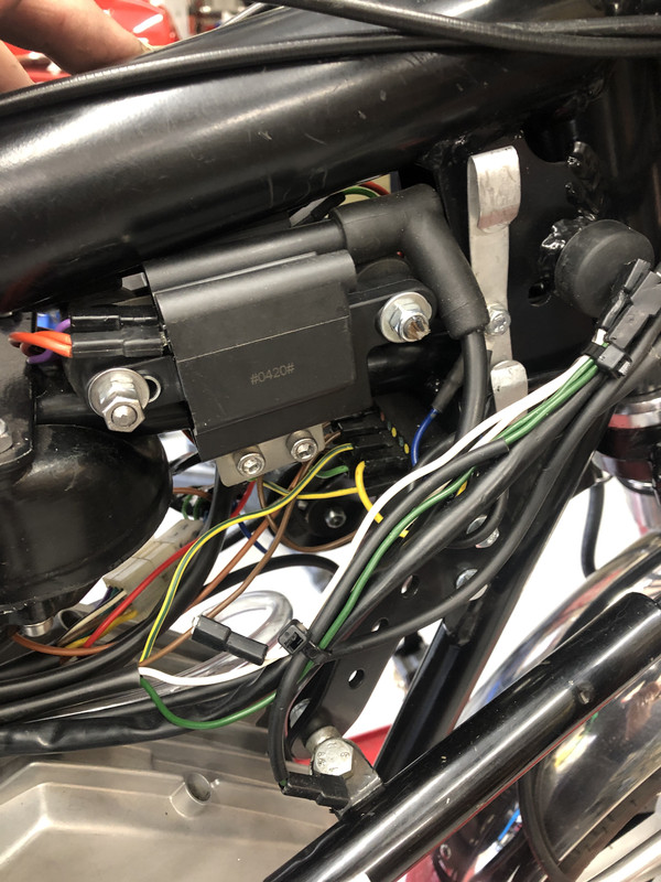
Next I made up a new section of harness long enough to reach from the space behind the battery up the center of the frame to the area where the new coils are mounted. I ran a red, green, purple and grey wire in a pvc sheathing and terminated the wire ends at the coils with new female spade terminals and plastic covers. The grey wire is spliced into the original grey wire that feeds the tachometer. The new red wire that connects the two coil + leads is terminated at the fuse box with a new female spade connection and plastic cover and then this red wire continues to the control box.
A stainless steel plate was made with one hole to fasten the plate between the rear fender upper mount and frame tab. The supplied ten pin control box is fastened to this plate using the supplied Velcro sheets.
The supplied terminal plugs were crimped to the four new wires I had made up along with a pair of new black ground wires. Then all ten wires were inserted into the control box and connections tightened with the supplied screwdriver.
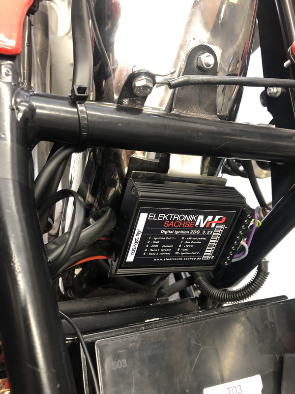
Once the connections were done the peel and stick Velcro sheets were stuck to the back of the control box and then the box stuck to the new stainless plate behind the battery.
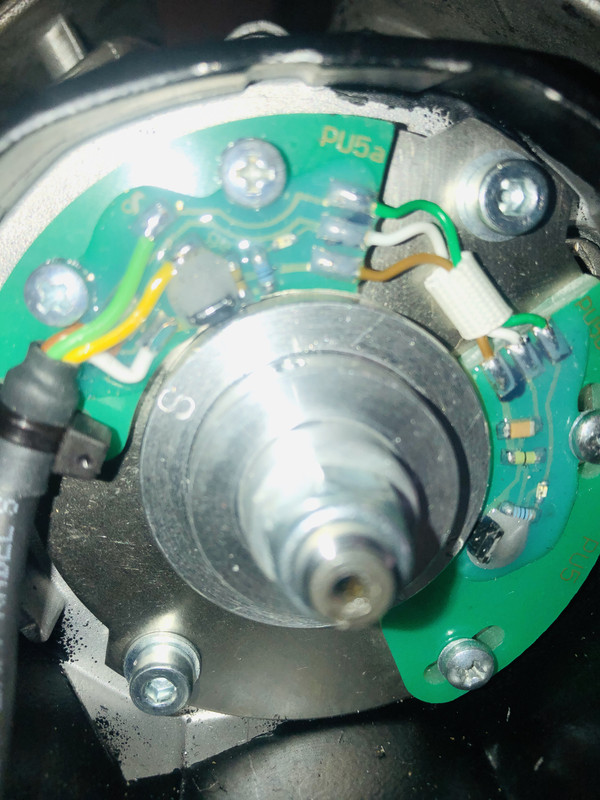
Back to the pick up plate the supplied magnetized ring is slipped over the new supplied spacer previously installed.
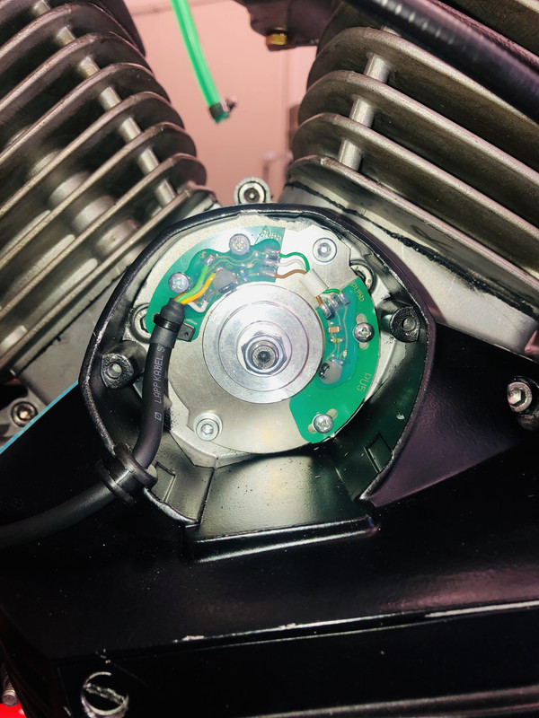
Rear piston was brought to TDC (PSM2), it does not matter if its on compression stroke. The ignition is then switched on and the magnetized ring rotated to align with 'S' stamped on the ring (does not matter which of the two 'S' marks are used) with the upper LED until the LED lights up. As soon as I turned on the key the LED lit. I then rotated the ring towards the 'N' mark stamped on the ring until the LED went off.
Then tighten the two small alan set crews on the adjustable ring. Turn the ignition OFF.
Install the spark plugs into the high tension leads and set the plugs near the cylinder heads. using the supplied small flat blade screw drive set the control box rotating advance switch to position zero (test).
Turn the ignition ON, both spark plugs should spark continuously and with a bright strong spark. Battery must be in good shape, manual says it will spark as low as 7 volts. My battery read 12.5 volts.
I am happy to report that on the TEST (zero) position both spark plugs emitted a continuous and very strong spark, Hurrah!
On the weekend I will reinstall the gas tank and hopefully the bike will fire up and run well, fingers crossed.
The kit arrived yesterday via DHL including a pair of Dyna mini coils.
https://www.elektronik-sachse.de/shopsy ... i-500.html
Installation is straightforward with the only challenge mounting the Dyna coils. I made up some brackets out of 18 gauge stainless steel sheet to tuck the coils into the positions previously occupied by the stock transducers.
To install the system simply disconnect the wires supplying the transducers;
green wire from fuse box to transducer with a jumper green to second transducer is disconnected, I just pulled the green wire out of the fuse box and folded it over a harness sheathing and zip tied it, same at the headstock area, folded green wires back against a harness and zip tied wire. My bike has the white ground wire connecting the two transducers and the continues to the fuse box, again remove white wire from fuse box, fold over and zip tie, ditto at the heads stock area.
Remove the pick up inspection plate, remove the 8mm nut (11mm socket head) securing the pick up rotating magnet, remove nut, special spacer washer and magnet, remove the two alan head fasteners retaining the pick-up assembly and remove the pick up assembly, disconnect the two red wires up to the transducers and then unplug the grey wire on the left hand transducer that supplies the tachometer. The special washer will not be used with the new system, only the nut.
Remove the two transducers, Remove the high tension leads from the transducers to reuse onto the new Dyna coils.
The two yellow wires from the original stator remain installed to the regulator / rectifier to continue to charge the battery.
The brackets for the Dyna coils were cut out of flat stainless sheet with a cut off wheel in a 4" grinder and finished with a flat file. Two 6mm holes for the coils and two 6mm holes to match the original transducer frame mounts.
The Dyna coils are dampened with rubber bungs I had from other projects. There is also a thick rubber washer between the two brackets at each hole through which the coils are secured. I used 6mm threaded rod with a nylock nut on each end to through bolt the two coils through the brackets. before bolting the coils together I installed the high tensions leads with the new rubber boots and plug clips crimped onto the ends of the high tension wires.
I then moved on to the pick up plate installation, install the new supplied steel spacer over the end of the cam shaft
and reinstall the nut over the protruding end of the cam shaft (no special washer used here)
The new supplied pick up plate with the LED sensors was installed using the two new alan head fasteners and washers. Attached to the new pick up plate is a four wire harness with a new rubber grommet, run the new harness up the front frame rail. I then ran the remainder of the harness to the space between the rear fender and battery.
Next I made up a new section of harness long enough to reach from the space behind the battery up the center of the frame to the area where the new coils are mounted. I ran a red, green, purple and grey wire in a pvc sheathing and terminated the wire ends at the coils with new female spade terminals and plastic covers. The grey wire is spliced into the original grey wire that feeds the tachometer. The new red wire that connects the two coil + leads is terminated at the fuse box with a new female spade connection and plastic cover and then this red wire continues to the control box.
A stainless steel plate was made with one hole to fasten the plate between the rear fender upper mount and frame tab. The supplied ten pin control box is fastened to this plate using the supplied Velcro sheets.
The supplied terminal plugs were crimped to the four new wires I had made up along with a pair of new black ground wires. Then all ten wires were inserted into the control box and connections tightened with the supplied screwdriver.
Once the connections were done the peel and stick Velcro sheets were stuck to the back of the control box and then the box stuck to the new stainless plate behind the battery.
Back to the pick up plate the supplied magnetized ring is slipped over the new supplied spacer previously installed.
Rear piston was brought to TDC (PSM2), it does not matter if its on compression stroke. The ignition is then switched on and the magnetized ring rotated to align with 'S' stamped on the ring (does not matter which of the two 'S' marks are used) with the upper LED until the LED lights up. As soon as I turned on the key the LED lit. I then rotated the ring towards the 'N' mark stamped on the ring until the LED went off.
Then tighten the two small alan set crews on the adjustable ring. Turn the ignition OFF.
Install the spark plugs into the high tension leads and set the plugs near the cylinder heads. using the supplied small flat blade screw drive set the control box rotating advance switch to position zero (test).
Turn the ignition ON, both spark plugs should spark continuously and with a bright strong spark. Battery must be in good shape, manual says it will spark as low as 7 volts. My battery read 12.5 volts.
I am happy to report that on the TEST (zero) position both spark plugs emitted a continuous and very strong spark, Hurrah!
On the weekend I will reinstall the gas tank and hopefully the bike will fire up and run well, fingers crossed.